SPC Automated Watering Kit
SPC Automated Watering Kit is a ease-to-use tool kit for you to develop a smart watering system for plants.
The kit implements two functions. One is to detect environment factors affecting plant growth such as soil moisture, another one is to water plants automatically through the moisture monitoring.
Individual pumps from the water reservoir delivers water over 1 meter (>3 feet) vertically to the plant pots.
Two solar panels supply 12 Volts, 180mA recharge the 12 Volt battery during the daylight and the 12 Volt battery supplies power to the moisture sensor electronics and power to the water pumps.
The digital solar controller can be configured to only supply power to the pumps and electronics for one hour after sunset in order to conserve power.
Parts can be purchased at Synthetic Physical Computing individually for maximum flexibility.
Possible (Cheap) Expansion Board for the Arduino Uno?
For a few months, many in the Arduino community have heard rumors about Iteadstudio’s release of a very low priced Arduino development board ($US 7-8). While there are clones of many varieties available, it is always interesting to know what is out there and to at least characterize it.
One of the Arduino Community active contributors, John Boxall of tronixstuff, received his Iteaduino Lite and wrote a review of the development board. Summary is that the microcontroller (LogicGreen LGT8F88) is a Chinese clone of the ATmega88A (with some extra things), which means 8k of Flash memory. Of course, I have no qualms with “green-tech”, but cutting back on Flash? It appears the reaction in the community is, “Wah?!”
They seem to have an answer to this on the simple spec page:
LGT8F88A based on LGT8XM, a deeply optimized 8bit RISC core. In order to maximize performance and parallelism, LGT8XM uses Harvard architecture – with separate memories and buses for program and data. Instructions are executed inside a 2-stage pipeline. 2-stage pipeline reduces useless fetch-stage, so decrease power consumption caused by flash memory. LGT8XM introduce a smart instruction cache, which can fetch more instructions one time, effectively decrease memory accessing operations. Based on our test, LGT8XM decrease about 40% power consumption caused by program memory compare to other 8bit architectures.
So, it might be interesting to compare the current consumption, but I am thinking the vast majority of the current consumption will be in the shield stack, so not very high on the concerns list. There has got to be something interesting.
What I did see in that specification? 32MHz @ 1.8 ~ 5V? There might be something here… I wonder if you could easily mount the Iteaduino Lite on the Uno?
One of the more features that can be found on a lot of Asian Arduino hardware is the two sets of offset header holes for allowing the boards to stack. For the development boards, I suspect it was for putting standard 0.1″ perf boards on Arduino derivatives.
Okay, the hardware to hardware interface is available, what about the software? The only real options are TWI/I2C (maybe One-
Wire) or the SPI interface. I am not sure if I am done stacking, so I will pick the Two Wire interface.

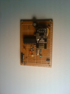
The board to board connections are simple with soldering only a pair of male pins for the 5V/Gnd and A4/A5 from the bottom of the Iteaduino Lite board.
Alright, now a good sketch is in order and I am not going to re-invent the wheel. From my search of the net, Nick Gammon (Another Arduino Community mainstay) has the most complete exploration study of Two-Wire or I2C for the Arduino that I can find. There is more TWI/I2C functionality that can be found on his site, but I liked these for the basic concept.
For the Uno (Master) (Pastebin here):
// Written by Nick Gammon
// Date: 18th February 2011
// Modified by Synthetic Physical Computing
// Date: 1st Febuary 2014
#include <Wire.h>
const int SLAVE_ADDRESS = 0x42;
// various commands we might send
enum {
CMD_ID = 1,
CMD_READ_A0 = 2,
CMD_READ_A1 = 3,
CMD_READ_A2 = 4,
CMD_READ_A3 = 5,
CMD_READ_D2 = 6,
CMD_READ_D3 = 7,
CMD_READ_D4 = 8,
CMD_READ_D5 = 9,
};
void sendCommand (const byte cmd, const int responseSize)
{
Wire.beginTransmission (SLAVE_ADDRESS);
Wire.write (cmd);
Wire.endTransmission ();
Wire.requestFrom (SLAVE_ADDRESS, responseSize);
} // end of sendCommand
void setup ()
{
Wire.begin ();
//TWBR = 12; //Uncomment for 400k
Serial.begin (9600); // start serial for output
sendCommand (CMD_ID, 1);
if (Wire.available ())
{
Serial.print (“Slave is ID: “);
Serial.println (Wire.read (), HEX);
}
else
Serial.println (“No response to ID request”);
} // end of setup
void loop()
{
int val;
sendCommand (CMD_READ_A0, 2);
val = Wire.read ();
val <<= 8;
val |= Wire.read ();
Serial.print (“Value of A0: “);
Serial.println (val, DEC);
sendCommand (CMD_READ_A1, 2);
val = Wire.read ();
val <<= 8;
val |= Wire.read ();
Serial.print (“Value of A1: “);
Serial.println (val, DEC);
sendCommand (CMD_READ_A2, 2);
val = Wire.read ();
val <<= 8;
val |= Wire.read ();
Serial.print (“Value of A2: “);
Serial.println (val, DEC);
sendCommand (CMD_READ_A3, 2);
val = Wire.read ();
val <<= 8;
val |= Wire.read ();
Serial.print (“Value of A3: “);
Serial.println (val, DEC);
sendCommand (CMD_READ_D2, 1);
val = Wire.read ();
Serial.print (“Value of D2: “);
Serial.println (val, DEC);
sendCommand (CMD_READ_D3, 1);
val = Wire.read ();
Serial.print (“Value of D3: “);
Serial.println (val, DEC);
sendCommand (CMD_READ_D4, 1);
val = Wire.read ();
Serial.print (“Value of D4: “);
Serial.println (val, DEC);
sendCommand (CMD_READ_D5, 1);
val = Wire.read ();
Serial.print (“Value of D5: “);
Serial.println (val, DEC);
delay (500);
} // end of loop
For the Iteaduino Lite (Slave) (Pastebin here):
// Written by Nick Gammon
// Date: 18th February 2011
// Modified by Synthetic Physical Computing
// Date: 1st Febuary 2014
#include <Wire.h>
const byte MY_ADDRESS = 0x42;
// various commands we might get
enum {
CMD_ID = 1,
CMD_READ_A0 = 2,
CMD_READ_A1 = 3,
CMD_READ_A2 = 4,
CMD_READ_A3 = 5,
CMD_READ_D2 = 6,
CMD_READ_D3 = 7,
CMD_READ_D4 = 8,
CMD_READ_D5 = 9,
};
char command;
void setup()
{
command = 0;
pinMode (2, INPUT);
digitalWrite (2, HIGH); // enable pull-up
pinMode (3, INPUT);
digitalWrite (3, HIGH); // enable pull-up
pinMode (4, INPUT);
digitalWrite (4, HIGH); // enable pull-up
pinMode (5, INPUT);
digitalWrite (5, HIGH); // enable pull-up
pinMode (A0, INPUT);
digitalWrite (A0, LOW); // disable pull-up
pinMode (A1, INPUT);
digitalWrite (A1, LOW); // disable pull-up
pinMode (A2, INPUT);
digitalWrite (A2, LOW); // disable pull-up
pinMode (A3, INPUT);
digitalWrite (A3, LOW); // disable pull-up
Wire.begin (MY_ADDRESS);
Wire.onReceive (receiveEvent); // interrupt handler for incoming messages
Wire.onRequest (requestEvent); // interrupt handler for when data is wanted
} // end of setup
void loop()
{
// all done by interrupts
} // end of loop
void receiveEvent (int howMany)
{
command = Wire.read (); // remember command for when we get request
} // end of receiveEvent
void sendSensor (const byte which)
{
int val = analogRead (which);
byte buf [2];
buf [0] = val >> 8;
buf [1] = val & 0xFF;
Wire.write (buf, 2);
} // end of sendSensor
void requestEvent ()
{
switch (command)
{
case CMD_ID: Wire.write (MY_ADDRESS); break; // send our ID
case CMD_READ_A0: sendSensor (A0); break; // send A0 value
case CMD_READ_A1: sendSensor (A1); break; // send A0 value
case CMD_READ_A2: sendSensor (A2); break; // send A0 value
case CMD_READ_A3: sendSensor (A3); break; // send A0 value
case CMD_READ_D2: Wire.write (digitalRead (2)); break; // send D2 value
case CMD_READ_D3: Wire.write (digitalRead (3)); break; // send D3 value
case CMD_READ_D4: Wire.write (digitalRead (4)); break; // send D4 value
case CMD_READ_D5: Wire.write (digitalRead (5)); break; // send D5 value
} // end of switch
} // end of requestEvent
Output looks like this:
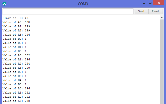
I must confess that is just two Arduinos attach via TWI/I2C, but when I do receive my Iteaduino Lite I am curious of the ADC performance running at 32 MHz above my Uno. Until then.
ATMEGA328P Internal Temperature Sensor Bias
While testing on it’s own, without any peripherals, the ATmega328P does a good job in temperature measurements. The question that comes to mind is, “What happens when this chip starts to source current?”.
For my little project, I am looking at 15mA pulse for the radio Tx and an occasional Tx LED blink of 13.6mA.
Since there are three LEDs on the board already, 40mA should be enough to test with.
Using the same sketch as the Hidden Response Accuracy in the ATMEGA328P, I commented out the LM35 measurements and added a Blink without Delay for the (3) LEDs.
Tests included were:
- Measure every second and toggle the LEDs every 10 seconds
- Measure every second and toggle the LEDs every 2 minutes
- Measure every second with the LEDs always ON
Results:

While there is an obvious bias with the “Always On” chip heating, the reduced duty cycles can help dissipate some of the heat generated internally. I would imagine 100mA total sourced current will make this a problem for a project requiring <3°C accuracy.
ATMEGA32U2 and LM35DZ Temperature Responses
Out of curiosity and the difficulty in finding a decent Arduino IDE sketch for measuring the internal temperature sensor in the ATmega32U4, I decided to post it here. Pretty much the same behavior on the measurement as the ATmega328, just a little different in implementation based on the datasheet section 24.6.
The sketch below has three measurements; the internal ATmega32U4 sensor, the LM35DZ with a Ring Buffer smoothing and the same LM35DZ with no smoothing.
Hidden Response Accuracy in the ATMEGA328P
UPDATED – See Below
Some people may have known already about the temperature sensor built into the ATMEGA8, 168, 328 series microcontrollers, but the most serious enthusiast would write off the 1°C resolution as just a coarse sensor of no practical use. I would have to say I was part of that group, until I compared the response between the two sensors.
The TI LM35DZ is a simple temperature sensor that has an accuracy of +/-0.5°C at 25°C and with 0.08°C of self heating, this should be sufficient to demonstrate the rough nature of the ATMEGA328’s internal temperature when compared to dedicated external sensor. The TO-92’s have the best Thermal Reponses on the datasheets and are the cheapest. Connection is straight-forward, +5VDC, Vout and Gnd with Vout to the ATMEGA328’s PC0 (Arduino pin A0).
For the ATMEGA328 internal sensor, adjustment of the voltage offset can be used to calibrate to another sensor.
The Arduino IDE sketch is as follows:
Basic Perf-board Mega1284
 Sooner or later, one finds the need to move the project from the breadboard to a more permanent setting. There are development platforms like the Arduino Uno, Mega2560 with stackable shields, or you may want to just wire one up on a through-hole perf-board. The layout of most development boards are certainly enticing, some projects require a little more flexiblity that stripboards and perf-boards can provide. For low power applications strip-boards and perf-boards really handy for leaving the regulator off for low power battery performance and then later, adding a regulator. The lack of inexpensive Mega1284P development boards make the perf-board an easy choice.
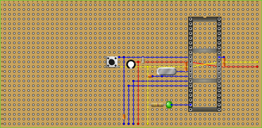
The kit you will need for the Basic Perf-board Mega1284 is as follows:
- (1) – ATMEGA1284P
- (1) – 40 Pin IC Socket (wide)
- (1) – 54 x 28 0.1″ spacing perf-board
- (1) – 16MHz Crystal
- (2) – 22pF ceramic capacitors
- (3) – 100nF ceramic capacitors
- (1) – 100uF 16-25 volt electrolytic capacitor
- (1) – 10K ohm resistor
- (1) – 1 x 6 pin header
- (10) – Feet of 30 gauge stainless steel wire
- (1) – DPST momentary switch
- (1) – USB2TTL FTDI convertor
The first thing to note about perf-boards is that the solder pads can pull up if the solder iron is applied too long (around 10 seconds). If you are not melting solder by 5 seconds, you will need to stop or you may damage the pad.
Step 1 – Placing and Soldering the IC Socket
Cut out 1 inch of the 30 gauge wire and connect pin 10 (VCC) to pin 30 (AVCC)
Place the IC Socket over the connection wire
Solder up the 40 pin IC Socket
On the backside of the perf-board, solder a piece of 30 gauge wire connecting pin 11 (GND) to pin 31 (GND)
Cut out 4 inches of 30 AWG wire and solder one end to pin 10 (VCC) and thread out to make connection with FTDI Vcc
Cut out 4 inches of 30 AWG wire and solder one end to pin 11 (GND) and thread out to make connection with FTDI GND
Place and solder a 0.1uF ceramic capacitor across pins 10 (VCC) & 11 (GND)
Place and solder a 0.1uF ceramic capacitor across pins 30 (AVCC) & 31 (GND)
Place and solder a 0.1uF ceramic capacitor across pins 32 (AREF) & 31 (GND)
Step 2 – Connecting the Crystal
Place the 16 MHz Crystal where one leg will make a straight connection to pin 12 (XTAL2)
Cut a piece of 30 AWG wire to connect the other leg to pin 12 (XTAL2)
Cut a piece of 30 AWG wire to connect the other leg to pin 13 (XTAL1)
With one of the 22pF ceramic capacitors, connect the lead between the Crystal and XTAL2 to GND
With another 22pF ceramic capacitor, connect the other lead between the Crystal and XTAL1 to GND
Step 3 – Connecting Reset and UART Communications
Cut out 4 inches of 30 AWG wire and solder one end to pin 9 (RST) and thread out to make connection with FTDI Reset three holes short of connecting to the reset pin on the header
Thread a 0.1uF ceramic capacitor lead into the same hole the 30 AWG (RST) line and solder
Thread the other lead and continue to connect to the FTDI Reset pin
With a 10k ohm resistor connect the 30 AWG (RST) line and 30 AWG (VCC) where close by
Place the DPST momentary switch to connect the 30 AWG (RST) line and the Ground (GND)
Cut out 4 inches of 30 AWG wire and solder one end to pin 14 (RXD0) and thread out to make connection with FTDI Tx
Cut out 4 inches of 30 AWG wire and solder one end to pin 15 (TXD0) and thread out to make connection with FTDI Rx
Step 4 – Finishing Up
Connect a 100uF/16-25V electrolytic capacitor on the 30 AWG (VCC) and (GND) lines (Negative on Ground).
Place an LED by pin 19 (Arduino D13) with the flatted side (Cathode) towards Ground and solder a lead from the Anode to pin 19
Place a 460 ohm resistor between the LED Cathode and Ground then solder the LED to the Resistor and the Resistor to Ground
Place the ATMEGA1284 microcontroller into the socket
Connect the FTDI
If the ATMEGA1284 is freshly bootloaded and everything is connected correctly, the LED should flash.

MEGA-1284 Logic Analyzer – Viewing UART Signals
Now that you have a MEGA-1284 Logic Analyzer, it is time to view some data signals. We will start with a UART off of another Arduino, since it is a fairly explicit communications protocol. I loaded the ASCIITable sketch from the Arduino IDE to generate the communications on the Arduino. Disconnect the USB and jumper from the power rails 5v0 and GND to the header pins 5v0 and GND on the Signal Arduino. Then simply connect Channel 0 (D16 or chip pin 22) on the MEGA-1284 Logic Analyzer to D1 (TX) of the Signal Arduino. You should be ready on the hardware side, so go ahead and plug the MEGA-1284 Logic Analyzer into the PC. Then, startup the Open Logic Sniffer client application.
Click on <Capture> and <Begin Capture> to open the “Connection” tab and verify connection to the MEGA-1284 by clicking the “Show device metadata” button. Information show populate the fields below the button. If not, you will have to verify the connection settings are correct.
Click on the “Acquisition” tab and change the “Sampling rate” to 20 kHz. At 9600 bps, 10 kHz should suffice, but I was getting noise in the data and the Noise filter is not developed yet for the MEGA-1284. Click on the “Triggers” tab and click a check in Mask 0 (Channel 0) and nothing in the value for Mask 0 (trigger will occur from a HIGH to a LOW).
MEGA-1284 Logic Analyzer
Eventually, the electronic hobbyist find themselves needing more complicated tools. One need that arises is to view into the world of the electronic pulses and gaze upon the communications.
One simple example of such a digital communication is an IR receiver. A more complicated example would be a I2C bus or UART communication. All of these can be addressed fairly simply with a logic analyzer.
The first thing that is needed is a sketch to load onto the ATMEGA1284:
Connecting USB to Serial/TTL to Breadboard “Mega-P”
Now, with a Breadboard Mega built out, we need a way to get programs or sketches onto the microcontroller. One of many tools is a USB to Serial or TTL (Transitor-Transitor Logic) breakout board. The most common is FTDI232RL, but there are others. This board will allow one to UPLOAD a sketch onto the ATmega1284 without disturbing the bootloader in Flash or the EEPROM. Other ways use a programmer that erase and overwrite the microcontroller and the bootloader will be no more. Of course, you can use the programmer to put the bootloader back, but not both at the same time.
Building the Breadboard “Mega1284-P”
Building your own breadboard microcontroller is both an educational exercise and satisfying. It gives one basic layout for future projects as well as a working development platform. Note, there are a many ways to achieve the the same circuit, so you may find another layout that you like better.
The basic start-up circuit looks like this:

